

Introduction to Diesel Particulate Filter (DPF) Systems
The widespread adoption of diesel particulate filters (DPFs) in modern diesel-powered vehicles has led to an increase in DPF-related faults, customer complaints, and costly repair procedures. This article aims to provide a comprehensive overview of DPF system design, history, regeneration strategies, diagnostic procedures, and fault handling to support accurate diagnosis and ensure component integrity across emission control systems.
The History of DPF Systems
In the early 2000s, some high-end or eco-focused diesel models began using DPFs, particularly in Europe. The use of DPFs became more widespread with the introduction of Euro 4 regulations in 2005, which pushed for lower particulate emissions. The U.S. market followed suit, with DPFs becoming mandatory for heavy-duty trucks in 2007 and light-duty diesel pickups and SUVs in 2008-2010.
The following timeline highlights key milestones in the development and implementation of DPF systems:
- Pre-2005: Limited use in high-end European diesels for smoke reduction and eco-branding.
- 2005: Euro 4 pushed for lower particulate emissions; some OEMs used partial filters or in-cylinder strategies.
- 2007: In the U.S, DPFs became mandatory for heavy-duty trucks.
- 2008–2010: The U.S adopted DFPs in light-duty diesel pickups and SUVs.
- 2009–2011: Euro 5 Full DPF integration became mandatory for new diesel passenger cars.
- 2010: It becomes standard in diesel passenger cars and crossovers, combined with SCR systems in the U.S.
- 2014: Euro 6 was introduced with tighter NOx limits and SCR systems; required higher efficiency and sensor integration.
The Future of Emissions Regulations
Looking ahead, Euro 7 regulations are set to expand emissions regulations to include brake/tyre particulates and non-exhaust emissions across all powertrains, including hybrids and EVs, from late 2026.
Understanding DPF Systems
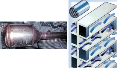
A DPF is constructed from a ceramic monolith, coated with precious metals such as platinum. Its internal structure resembles a catalytic converter but features alternating blocked channels, forcing exhaust gas through porous walls where particulates are trapped. The surface area of a DPF can be equivalent to three football fields, allowing for high filtration efficiency.
DPF Regeneration Processes
DPF regeneration is a process that removes soot from the filter to prevent the buildup of exhaust back pressure, which can increase fuel consumption, reduce power output, and potentially cause engine damage. The primary reason for soot removal is to prevent the buildup of exhaust back pressure. There are several ways to perform a DPF Regeneration:
Passive Regeneration
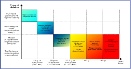
Passive regeneration occurs under continuous driving with high exhaust temperatures (motorway/highway operation) and requires no ECU intervention.
Active Regeneration
Active regeneration is commanded by the PCM when the excess soot build-up thresholds are met. During regeneration, the exhaust gases reach temperatures above 550°C (1000°F). Active regeneration requires:
- Minimum vehicle speed (typically >30 mph)
- Extended drive duration (20–30 mins)
- No system faults
- At least ¾ tank of fuel
Forced Regeneration
Forced regeneration is initiated via scan tool and requires full system readiness. It must only be performed under correct preconditions to avoid thermal overload, catalyst damage, or incomplete burn cycles.
DPF Diagnostic Procedures and Fault Handling
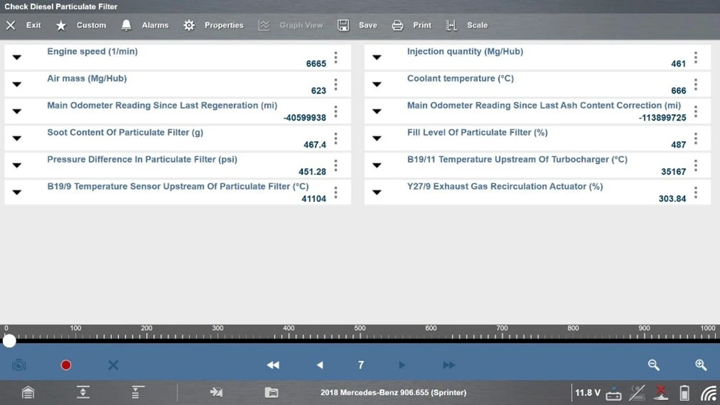
DPF diagnostic procedures involve checking live data and performing the DPF Pressure test using a scan tool. The following preconditions and fault dependencies must be considered:
• Faulty glow plugs
• Inoperative or leaking EGR system
• Incorrect fuel injection calibration
• Sticking VGT or wastegate control
• Malfunctioning ambient air sensor
• Oil degradation beyond the threshold
• AdBlue® system faults or low-DEF levels
• DPF pressure sensor deviation
• Exhaust temperature sensors out of range
• Fuel level below threshold (¾ of a tank)
Note: Even with a scan tool, initiating forced regeneration without meeting these criteria can cause severe engine overloading, damage the oxidation catalyst, or trigger permanent PCM DTCs.
DPF Pressure Values
Normal differential pressure values are:
• Idle: 2–10 millibar
• 3000 RPM (no load): 30–40 millibar
Always compare against OEM-specific values, as variations exist across platforms, including PSA Group®, VW®, Ford®, BMW®.
SCR and AdBlue Systems
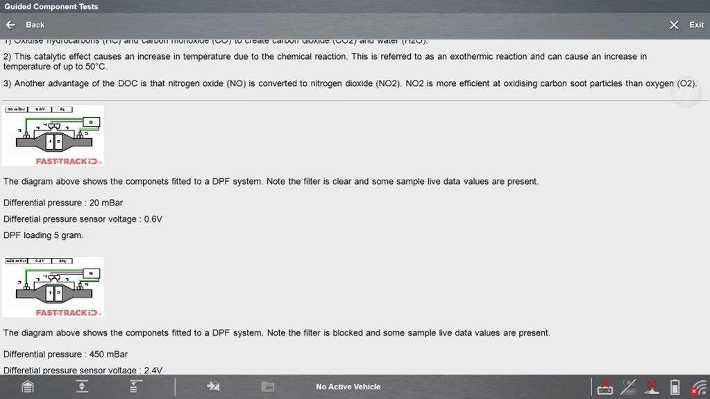
In modern diesel engines, Selective Catalytic Reduction (SCR) and the Diesel Particulate Filter (DPF) work together as part of a multi-stage emissions control system. The SCR system uses urea, also known as diesel exhaust fluid (DEF) in North America and AdBlue in Europe, to reduce NOx emissions.
The engine control unit (ECU) monitors and controls the SCR and DPF systems using data from:
• NOx sensors (pre and post SCR)
• DPF differential pressure sensors
• Exhaust temperature sensors
• DEF quality and level sensors
If anything is out of specification, it can trigger regeneration, adjust DEF dosing, log DTCs, or derate or disable engine start.
Conclusion
Understanding DPF systems, including their history, design, regeneration processes, and diagnostic procedures, is crucial for accurate diagnosis and repair. By following the guidelines and best practices outlined in this article, technicians can ensure component integrity and avoid costly mistakes. For more information on DPF systems and diagnostic procedures, visit Here